
04 / 05   Distortion

Application note

Geometric Distortion and Image Mapping

Measure departures from the intended geometry and define the distortion convention before comparing results.

Distortion changes where image content appears. A camera maps object positions to sensor coordinates; a display or projector maps commanded coordinates to visible positions. Either path can bend lines or change local scale without necessarily blurring a small feature. Measurement requires an explicit ideal mapping, because magnification, perspective, and optical distortion describe different departures from geometry.

Define the position error

For a rotationally symmetric mapping, compare measured image height rr with ideal image height r0r_0:

δ(r0)=100r−r0r0%\delta(r_0)=100\frac{r-r_0}{r_0}\%

At nonzero field radius, negative radial distortion corresponds to barrel distortion and positive to pincushion distortion under this convention. A simple radial model is:

r=r0(1+k1r02+k2r04+⋯ )r=r_0\left(1+k_1r_0^2+k_2r_0^4+\cdots\right)

The coefficient units depend on the coordinate normalization. Complex lenses can combine barrel and pincushion behavior across the field, so one corner percentage may conceal a change of sign. Decentering effects require additional terms beyond a radial model.
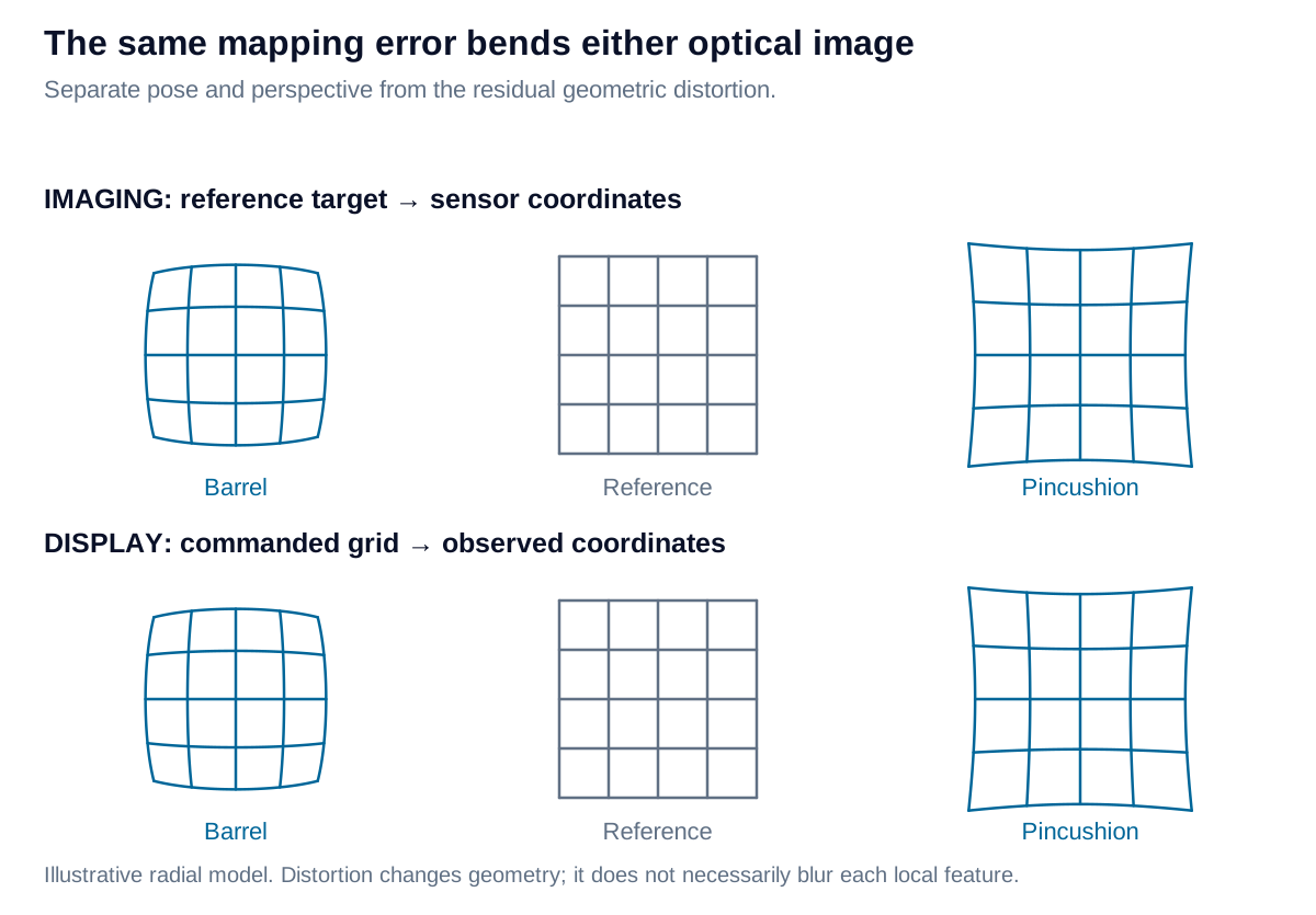
Imaging maps a reference grid to sensor positions; display projection maps commanded positions to a visible grid. Barrel and pincushion distortion bend either grid in the same geometric sense.

View diagram at full size

Imaging: calibrate object-to-sensor geometry

Image a dimensionally characterized grid or dot target at the intended working distance. Estimate feature centers, account for target pose, and fit the camera mapping. Perspective from a tilted target should not be mistaken for lens distortion. Target flatness, feature localization, and calibration coverage influence the recovered parameters.

Report displacement vectors and residual errors across the usable field, ideally in pixels and application units. A low fitting residual on the calibration data does not establish independent measurement accuracy. Validate with separate positions or reference dimensions. Lens focus changes, mechanical movement, and temperature can require renewed calibration.

Display: calibrate commanded-to-viewed geometry

Display a grid and measure its visible coordinates using a calibrated camera or other suitable metrology. Projection optics, screen shape, alignment, and viewing position can all contribute. For near-eye systems, eye position and the specified angular coordinate system are part of the measurement geometry.

Remove or model the measuring camera’s own distortion before attributing all observed bending to the display. Prewarping can correct a stable mapping, but resampling consumes spatial resolution and cannot create missing field coverage. Validate the corrected grid, local scale, and usable image boundary at representative viewing positions.

Keep TV distortion separate from radial distortion

TV distortion summarizes bending near the picture boundary; it is not the maximum radial position error. For the SMIA-style full-height convention shown here:

A=A1+A22,TVSMIA=100A−BB%A=\frac{A_1+A_2}{2},\qquad TV_{\mathrm{SMIA}}=100\frac{A-B}{B}\%

A1A_1 and A2A_2 are the picture’s full vertical heights at its left and right edges; BB is its full height at horizontal center. Barrel bending gives A<BA<B and a negative value. State the convention with the number: a traditional single-edge displacement divided by full picture height has half the magnitude for a vertically symmetric pattern.
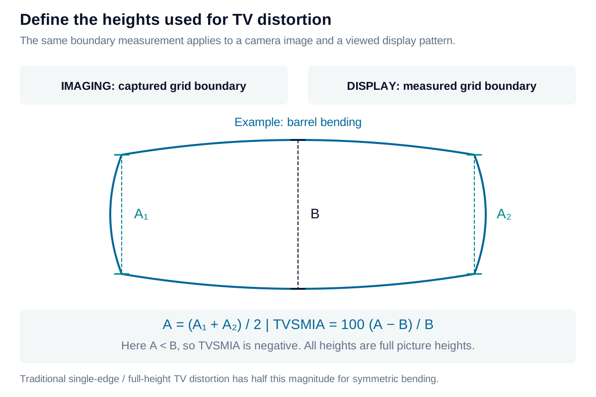
A shared measurement diagram defines left and right full-picture heights A1 and A2 and the central height B. The same geometry can be extracted from a camera image or a measured display grid.

View diagram at full size

Neither TV nor radial distortion alone captures keystone, local warping, or all asymmetric errors. Preserve the coordinate map and measurement setup alongside the summary metric. The calculator illustrates declared radial and TV definitions; a production calibration needs spatial data and independent verification.

Iris Optics can develop camera and display mapping calibrations, separate device geometry from measurement-system error, and verify whether the corrected system meets dimensional or visual requirements.

Explore the model

Radial and TV distortion

Compare an image or display point with its ideal radial position, then calculate TV distortion from an independent set of full image heights.

Change the values to update the results and visualization.

Signed radial distortion
-2 %
Radial displacement
-0.2 mm
SMIA TV distortion
-2 %
Single-edge / full-height TV (symmetric)
-1 %

The plot joins the origin to the radial measurement only; it is not a fitted distortion curve. The independent full-height measurements determine the TV metrics.

Radial and TV distortion: interactive plotMeasured radial coordinate / mm against Ideal radial coordinate / mm. No-distortion reference; Selected point from origin.002.22.24.44.46.66.68.88.81111Ideal radial coordinate / mmMeasured radial coordinate / mm
No-distortion referenceSelected point from origin
Formula & assumptions

Radial distortion = 100(rmeasured − rideal)/rideal. Separately: A = (A₁ + A₂)/2; SMIA TV = 100(A − B)/B.

Radial distances share a declared center after pose, magnification and intended projection are accounted for. Negative radial values are inward displacements; the origin has no defined percentage. TV inputs are independent top-to-bottom spans at the sides and center of a near-full-field rectangle. A traditional single-edge bow divided by the full center height gives half the SMIA percentage for the same vertically symmetric geometry. These summary values do not fit a full distortion model.

Explore the model

Explore a radial distortion model

Visualize a shared forward mapping for a camera image or a displayed/projected grid.

Change the values to update the results and visualization.

Mapped radius
0.92
Radial scale
0.92 ×
Signed radial distortion
-8 %

A positive offset from the diagonal is outward displacement; a negative offset is inward displacement. This forward model is shared by imaging and display geometry when the coordinate definitions match.

Explore a radial distortion model: interactive plotDistorted normalized radius against Undistorted normalized radius. Undistorted reference; Forward radial model.000.20.210.40.420.60.630.80.8411.05Undistorted normalized radiusDistorted normalized radius
Undistorted referenceForward radial model
Formula & assumptions

rd = ru(1 + k₁ru² + k₂ru⁴). All radii use one normalization and one distortion center.

A forward radial-only teaching model on the unit-radius disk. Coefficients are meaningful only with a specified normalization. Inputs that fold the mapping anywhere in that disk are rejected. The plot is a radius mapping, not calibrated rectification; no tangential/decentering terms, homography, eye position, projection calibration or inverse solver are included.

From estimate to application

Connect geometric fidelity to your application.

Define a camera calibration, display geometry test, or projection correction around the field, viewing conditions, and positional tolerance you need.

Review your geometric requirements