
An illuminated part, a display, and a printed label can look similar while producing very different spectra. Their behavior under a lighting change follows from how they generate, scatter, transmit, and absorb light. The useful distinction is between adding radiant contributions and selectively attenuating an incident spectrum.
Identify the physical mechanism
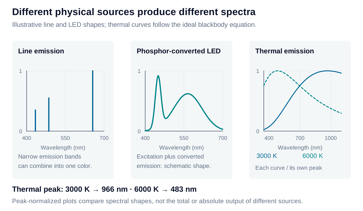
Emission creates outgoing light from an energy source. Gas discharges can produce narrow spectral lines associated with atomic transitions. Direct-emitting LEDs produce finite spectral bands; phosphor-converted LEDs combine excitation light with broader converted emission. A thermal emitter produces a continuous spectrum whose distribution changes with temperature.
For an ideal blackbody, the wavelength of maximum spectral radiance follows Wien’s displacement law:
At 3000 K, that peak lies near 966 nm, outside the visible band. Visible appearance depends on the visible portion of the entire spectrum, not simply its peak wavelength. A quoted color temperature also does not identify a unique LED spectrum.
Ordinary reflection redirects incident radiation; it need not involve absorption followed by lower-energy re-emission. Fluorescence is a distinct process that couples excitation and emission wavelengths. Scattering can also select wavelengths: for particles much smaller than the wavelength, the Rayleigh model predicts a strong inverse-fourth-power wavelength dependence. Interference and refraction provide other routes to selective color.
Add light before encoding it
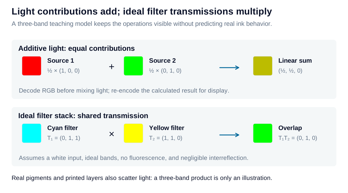
Independent, mutually incoherent sources contribute additive spectral power:
The same addition applies to linear XYZ values or correctly defined linear-light RGB components. Coherent fields may interfere and require a field-based treatment. Encoded image values must be decoded before a physical light mixture is calculated.
An RGB display controls three primary contributions. Their spectra and usable intensities define its gamut; the letters alone do not establish a standardized color. In an LCD, the backlight and subpixel filters jointly shape those primary spectra. In an emissive display, each primary directly supplies its outgoing light.
Multiply ideal filter transmissions
For two independent, nonfluorescent filters with negligible interreflection:
A band transmitted by one filter can be removed by the other. In a three-band teaching model, ideal cyan transmits green and blue, while ideal yellow transmits red and green. Their overlap passes green. Real filter edges, leakage, angle dependence, and surface reflections determine the actual result.
Printing is also subtractive, but multiplying three RGB numbers is not a predictive ink model. Ink absorption, particle scattering, paper reflectance, layer thickness, and spatial halftones all contribute. CMYK adds a black channel to control dark reproduction and ink use; process characterization remains necessary.
For color inspection, stabilize the source spectrum as well as its output level. A camera can report different channel values from the same coating when the source changes, even after a neutral reference appears balanced. The calculators below separate linear-light mixing from an ideal filter-stack calculation at one selected wavelength.