
An optical interface changes the direction available to transmitted light. This behavior determines how a lens focuses, how a prism redirects a beam, and how a protective window affects an imaging path. The starting point is the refractive index on each side of the interface and the angle at which light arrives.
Measure angles from the normal
The surface normal is perpendicular to the interface at the point where the ray arrives. Both the incident angle and transmitted angle are measured from this normal. Snell’s law connects those angles:
The dimensionless indices and describe the incident and transmitted media. A higher transmitted index reduces the angle to the normal; a lower index increases it, provided a transmitted ray exists. At normal incidence, the ray continues along the normal even when the index changes.
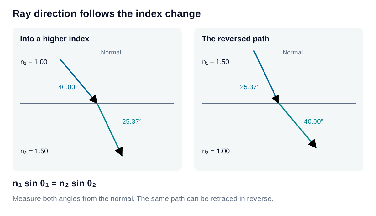
For , , and , the transmitted angle is approximately . Reversing the propagation direction through the same interface retraces that path. A curved surface applies the same rule locally, but its normal changes with position; this is how a lens redirects different rays toward an image.
Recognize the transmission boundary
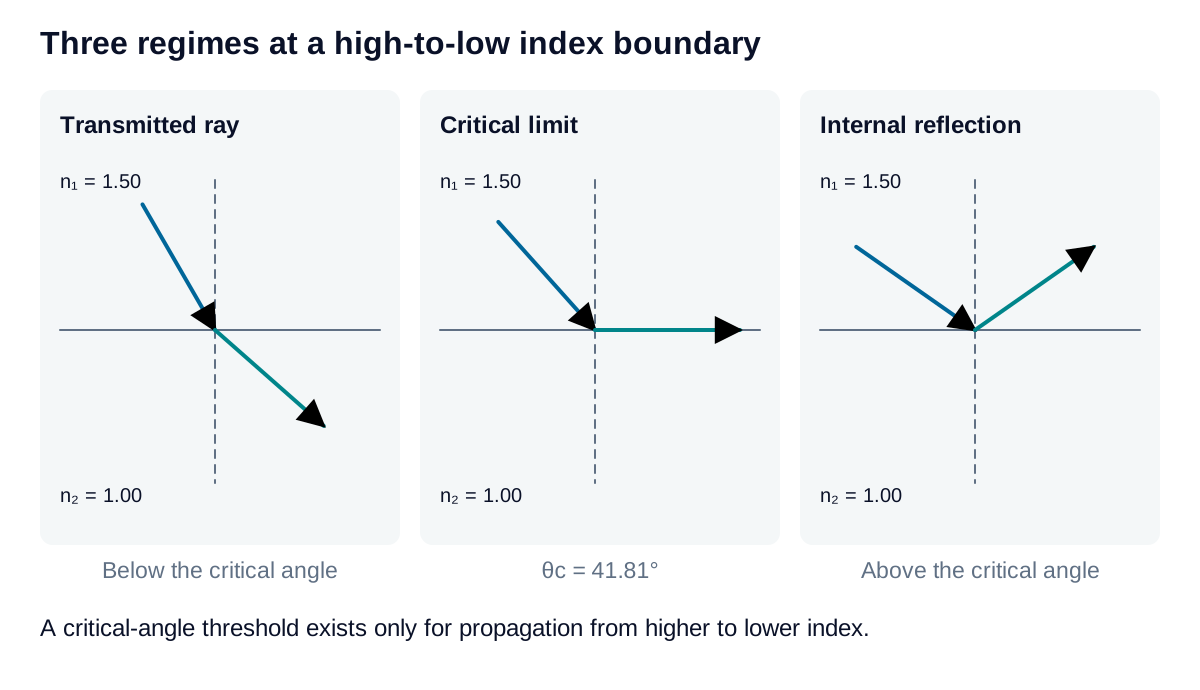
When light travels from a higher to a lower index, the transmitted ray approaches the interface as incidence increases. The critical angle is:
At this boundary, the limiting transmitted direction is parallel to the surface. Above it, total internal reflection replaces the propagating transmitted ray. For an index change from 1.50 to 1.00, ; incidence at therefore produces total internal reflection. There is no corresponding threshold when entering an equal or higher index.
Apply the result to an optical path
Use indices specified at the operating wavelength. Refraction predicts direction; it does not by itself determine how much optical power is transmitted or reflected. Surface coatings, polarization, and absorption require additional analysis.
For a window or prism, follow each interface in sequence and use its own local normal. A valid ray at the entrance does not guarantee transmission at the exit. The calculators below separate transmitted direction from the critical-angle check, providing a useful first assessment before evaluating a complete optical assembly.