
02 / 05   Refracting surfaces

Application note

Imaging by Refraction

Locate apparent and real images formed by a flat or curved optical interface.

Refraction changes more than the direction of an individual ray. A group of rays leaving one object point can converge at a new location or appear to originate from one. That location is its image. A single interface can therefore shift the apparent position of a feature or provide focusing power before a complete lens is introduced.

Apparent depth at a flat interface

A feature viewed through an index boundary may appear displaced along the viewing direction. For observation close to the surface normal, its apparent depth is:

dapparent=dactualn2n1d_{\mathrm{apparent}}=d_{\mathrm{actual}}\frac{n_2}{n_1}

Here, n1n_1 is the index surrounding the object and n2n_2 is the index on the observer’s side. Both depths are positive distances from the interface. A feature 18 mm beneath a surface in an index-1.50 medium appears 12 mm deep when viewed from air with index 1.00.

Derivation: apparent depth from Snell's law

Take a ray from an object at depth dactuald_{\mathrm{actual}}. It reaches the flat interface a horizontal distance xx from the point directly above the object. Its incident and transmitted angles, θ1\theta_1 and θ2\theta_2, are measured from the surface normal.

Extend the transmitted ray backward until it meets the normal through the object. That intersection defines its apparent depth. The two right triangles give:

tan⁡θ1=xdactual,tan⁡θ2=xdapparent\tan\theta_1=\frac{x}{d_{\mathrm{actual}}},\qquad \tan\theta_2=\frac{x}{d_{\mathrm{apparent}}}

Snell’s law connects the angles:

n1sin⁡θ1=n2sin⁡θ2n_1\sin\theta_1=n_2\sin\theta_2

For rays close to the normal, sin⁡θ≈tan⁡θ\sin\theta\approx\tan\theta. Substitute the triangle relationships:

n1xdactual≈n2xdapparentn_1\frac{x}{d_{\mathrm{actual}}}\approx n_2\frac{x}{d_{\mathrm{apparent}}}

Cancel the common nonzero xx and rearrange:

dapparent≈dactualn2n1d_{\mathrm{apparent}}\approx d_{\mathrm{actual}}\frac{n_2}{n_1}

The axial ray alone does not locate the image; nearby rays establish this limiting depth. Their backward extensions approximately share a virtual image point. At larger angles the intercept depends on the ray angle, so the simple depth ratio no longer describes a single exact image.
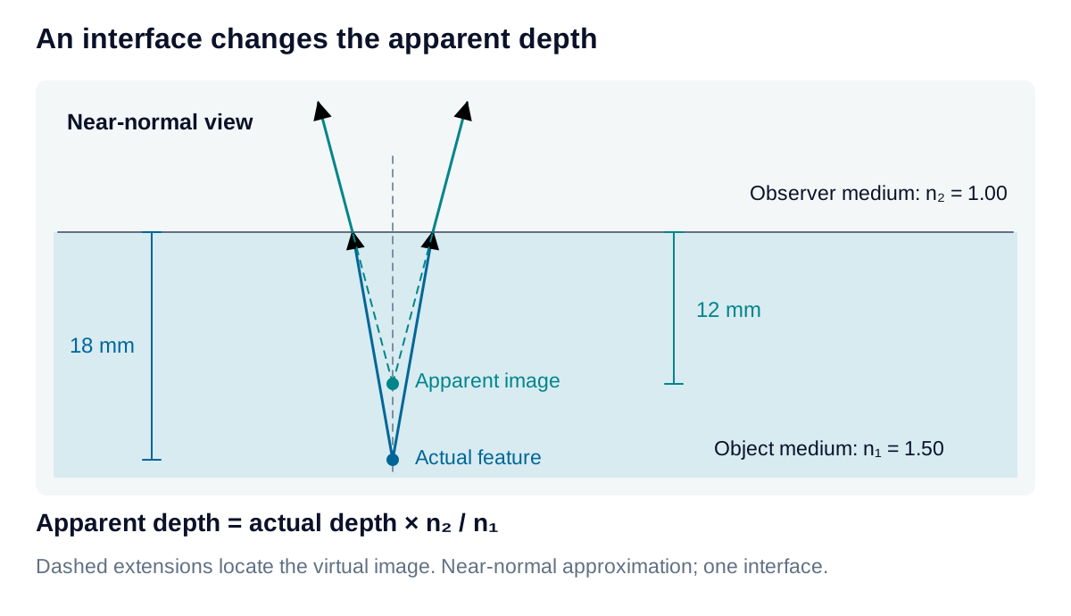
Rays leaving a submerged feature refract at a flat boundary; their backward extensions locate a shallower apparent image.

View diagram at full size

The apparent image is virtual: the transmitted rays do not physically converge there. This depth relation is useful when estimating focus through a transparent boundary, but it assumes near-normal viewing through one interface. An oblique view or an additional window surface requires a more complete ray model.

Image formation at a curved surface

A spherical interface has a different normal at each ray intersection. In the paraxial approximation, its image location follows:

n1s+n2s′=n2−n1R\frac{n_1}{s}+\frac{n_2}{s'}=\frac{n_2-n_1}{R}

The real object distance ss is positive on the incident side. The image distance s′s' is positive for a real image in the transmitted medium and negative for a virtual image on the incident side. The radius RR is positive when the center of curvature lies in the transmitted medium. All distances use the same units and are measured from the surface vertex.
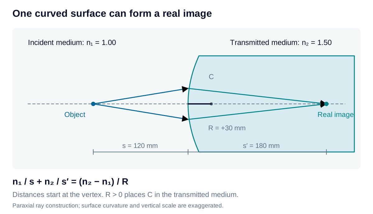
A spherical refracting surface redirects paraxial rays toward a real image in the second medium; object distance, image distance, and radius use explicit reference points.

View diagram at full size

For n1=1.00n_1=1.00, n2=1.50n_2=1.50, R=30R=30 mm, and s=120s=120 mm, the image forms at s′=180s'=180 mm. Moving the object to s=60s=60 mm produces collimated output instead of a finite image.

Separate image position from image scale

Across different indices, transverse magnification includes the index ratio:

m=h′h=−n1s′n2sm=\frac{h'}{h}=-\frac{n_1s'}{n_2s}

The first example gives m=−1m=-1: equal image size with inverted orientation. These results describe rays near the optical axis and a single refracting surface. Larger ray angles introduce departures from the approximation, and any subsequent exit surface changes the final image. Use the estimates to establish geometry before evaluating a practical lens or inspection window.

Explore the model

Spherical refracting surface

Locate the paraxial image formed by one spherical interface.

Change the example values to update the results and diagram. Use the stated units and sign convention.

Positive; measured upstream from the surface or thin lens.

Positive: center of curvature downstream. Negative: center upstream. Zero is invalid.

Signed image distance, s′
180mm
Transverse magnification
-1×
Image classification
real, inverted

Distances follow the sign convention described below.

Spherical refracting surface: updated diagramObject is upstream. Signed image distance 180 mm and transverse magnification -1. Real downstream image.ObjectSurfaceReal images′ = 180 mm · m = -1
Input-responsive schematic; not to scale. Scroll horizontally on narrow screens. Positions illustrate the calculated conjugates; this is not a full ray trace.
Formula & assumptions

s′ = n₂ / [(n₂ − n₁)/R − n₁/s]. Transverse magnification m = −n₁s′/(n₂s).

Single interface, small paraxial angles, real object s > 0. The outgoing medium extends beyond the surface. Positive s′ is downstream and real; negative s′ is upstream and virtual. A denominator indistinguishable from zero within a few arithmetic rounding units is reported as collimated, with no finite transverse image magnification.

Explore the model

Apparent depth

Estimate depth seen across a planar interface near the normal.

Change the example values to update the results and diagram. Use the stated units and sign convention.

Apparent depth
12mm
Apparent depth: updated diagramActual depth 18 mm; apparent depth 12 mm, both below the plane interface.Observer side · near-normal viewActual 18 mmApparent 12 mm
Input-responsive schematic; not to scale. Scroll horizontally on narrow screens. Positions illustrate the calculated conjugates; this is not a full ray trace.
Formula & assumptions

Apparent depth = actual depth × observer index / object index.

Plane interface and small viewing angles near its normal. Apparent depth is the positive depth of the virtual image on the object side. Oblique viewing, curved interfaces, and multiple windows require a different model.

From estimate to application

Connect interface geometry to measurement geometry.

Windows, liquids, and curved surfaces can change where a feature appears. Share the viewing geometry and the measurement you need to make.

Review your imaging geometry