
An eye and a camera both collect light and form an image on a sensitive surface. The useful comparison is the focusing task: rays from each object point must arrive within a sufficiently small region of the retina or sensor. The two systems solve that task differently, so a simple camera model should not be mistaken for a complete model of vision.
Two ways to maintain focus
In the eye, the cornea supplies much of the optical power, while changes in the crystalline lens support accommodation. The retina remains approximately fixed. In a camera, focusing commonly moves a lens or internal lens groups relative to the sensor. Some cameras use a fixed-focus arrangement with a limited acceptable object range.
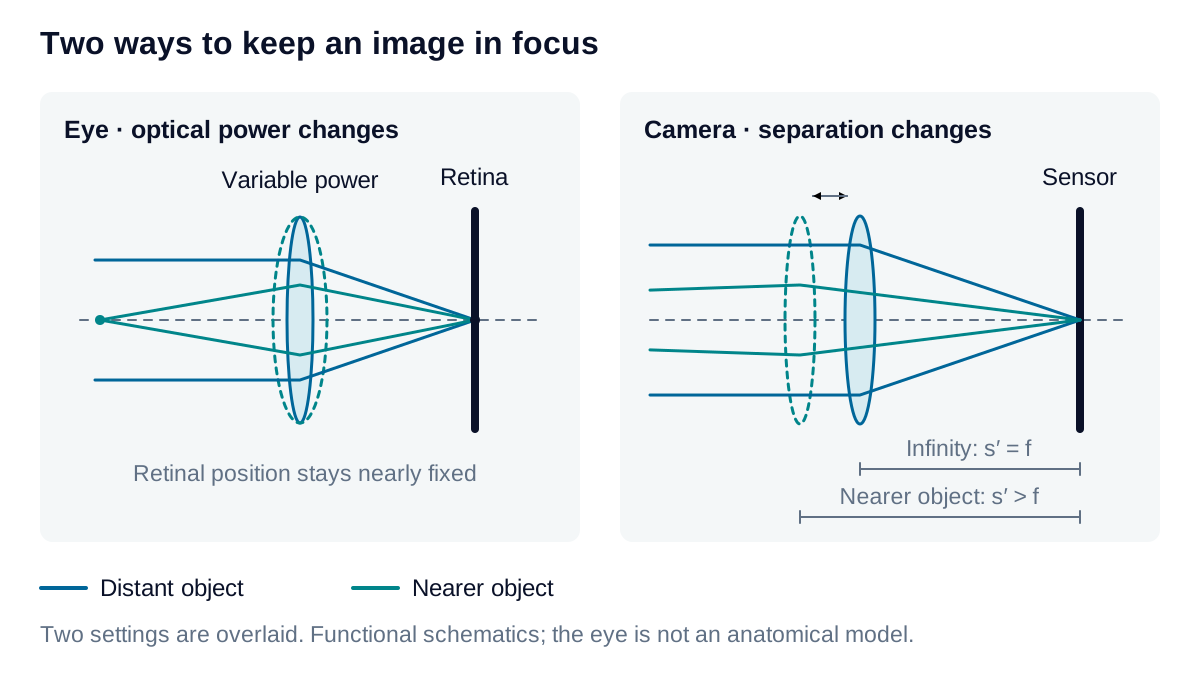
Both form a real, inverted optical image. Image orientation, however, says nothing by itself about sharpness. Aperture, aberrations, diffraction, sampling, and motion all influence the detail that survives. A geometric focus calculation addresses only one part of that performance requirement.
Estimate camera focus and field
For a positive thin lens in air imaging a real object beyond focus:
Here , , and are focal length, object distance, and image distance. is the additional image distance compared with infinity focus, is sensor width, and is the corresponding object-field width. Use consistent length units. Distances start at the thin-lens plane; a real assembly requires its principal-plane locations.
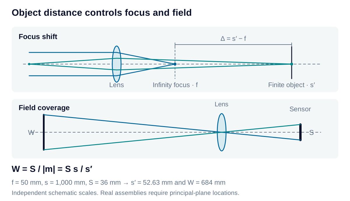
For mm, mm and mm, the model gives mm, 2.63 mm beyond infinity focus, and a 684 mm field. Internal-focusing lenses need not follow this mechanical extension directly. Whether a smaller focus error is acceptable depends on the permitted blur and aperture, not distance alone.
Express the change as vergence
Optometrists express lens power in diopters: one diopter is one inverse meter. For an ideal thin lens in air, write all distances in meters and convert the lens equation into a power balance:
Here is a positive focusing demand for a real object, and is the convergence required at the fixed image plane. These are named reciprocal-distance terms. Clinical signed vergence instead assigns a negative value to incident diverging light; the expander below connects the conventions.
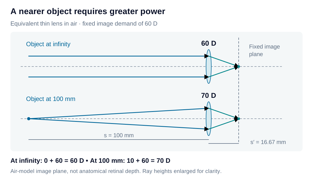
Consider a deliberately simplified air-lens model with a fixed image demand of 60 D. Its image plane lies m, or 16.67 mm, behind the equivalent lens. This is a model distance, not anatomical retinal depth.
| Object position | Object demand | Image demand | Required total power |
|---|---|---|---|
| Infinity | 0 D | 60 D | 60 D |
| 100 mm away | 10 D | 60 D | 70 D |
The near object requires 10 D more power while the image plane stays fixed. For an illustrative component budget, assign 40 D to a fixed element and 20 D to an adjustable element at the same plane; increasing the latter to 30 D gives the two totals. This mimics the cornea’s largely fixed contribution and the lens’s accommodation, without asserting a universal 40 + 20–30 D anatomical decomposition or a 100 mm near point for every eye.
Derivation: diopters, accommodation, and the eye model
Connect the signs. For a real object at positive distance , incident light diverges. Its signed vergence is ; a real image at positive distance requires outgoing vergence . The equivalent optical power changes vergence according to:
Distances are in meters and vergences and power are in diopters. For an equivalent optical system, distances start at its respective principal planes. In air on both sides, , recovering the thin-lens equation above. The positive object-demand term is , not itself.
Hold the image condition fixed. For the air-lens example, infinity requires:
For a real object at m, the incident vergence is D, so:
Subtracting the two conditions gives the relative accommodation demand in air:
Thus 0.25 m corresponds to 4 D and 0.10 m to 10 D. This is required focusing change, not a measurement of an individual’s available accommodation or an eyeglass prescription. Accommodation capacity varies, notably with age.
Distinguish the model from the eye. The eye’s image space contains vitreous with an index near 1.336, not air. In a reduced-eye model with 60 D of equivalent power at infinity, the image-side focal distance is:
That distance begins at the rear principal plane; it is not the cornea-to-retina axial length. The 16.67 mm result belongs to the air-lens illustration. Neither number by itself locates all the physical surfaces of an eye.
The anatomical cornea and crystalline lens also occupy separate planes. For two ideal thin elements of powers and , separated by distance in a medium of index , their equivalent power is:
Here is in meters. Direct addition follows only when the separation term can be neglected. A real eye also has multiple surfaces, lens thickness, and a varying lens refractive index. The 40 + 20–30 D budget is therefore a teaching illustration, not a clinical eye calculation.