
A lens maps the inspection field onto the sensor. Magnification determines field coverage and object-space sampling, while optical performance determines how much feature contrast reaches the image. A measurement lens therefore requires both a geometric specification and an image-quality requirement across the intended field and part-depth range.
Field coverage
For a centered rectangular field and approximately uniform magnification, the largest magnification that covers both required axes is:
are active sensor dimensions in mm, is positive magnification magnitude, and is pixel pitch in mm/pixel. gives the corresponding object-space sampling. These relations assume a planar field with approximately uniform scale. Significant distortion requires a spatially calibrated mapping.
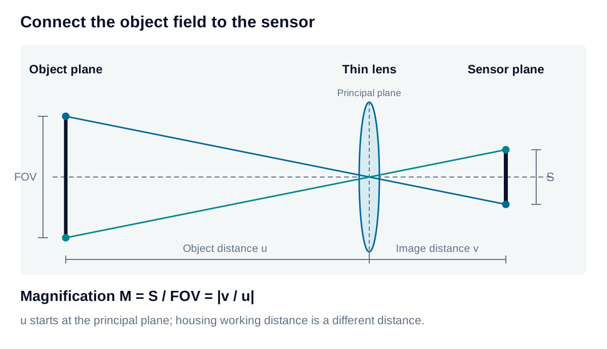
A 1,920 × 1,200 sensor with 4.5 µm pixels has an active area of 8.64 × 5.40 mm. For a required field of 92.4 × 59.4 mm, produces 95.04 × 59.4 mm coverage and 0.0495 mm/pixel sampling. The aspect-ratio mismatch leaves extra horizontal coverage; cropping reduces the usable field.
Focal length
For a thin-lens model with object distance :
The focal length and object distance are in mm. At mm and , the estimate is 20.83 mm. Optical object distance is measured from the object-side principal plane. Mechanical working distance is usually measured from the lens housing, so substituting it introduces an approximation. Manufacturer conjugate and mechanical data establish the geometry of a real lens, particularly for telecentric, macro, and complex assemblies.
Image quality across field and depth
The usable image circle must cover the sensor diagonal with acceptable corner illumination and resolution. Modulation transfer function (MTF) describes contrast transfer at different spatial frequencies. Lens evaluation uses the relevant frequency at the operating wavelength, aperture, magnification, and field position. Convert object-space frequency to image-space frequency by dividing by .
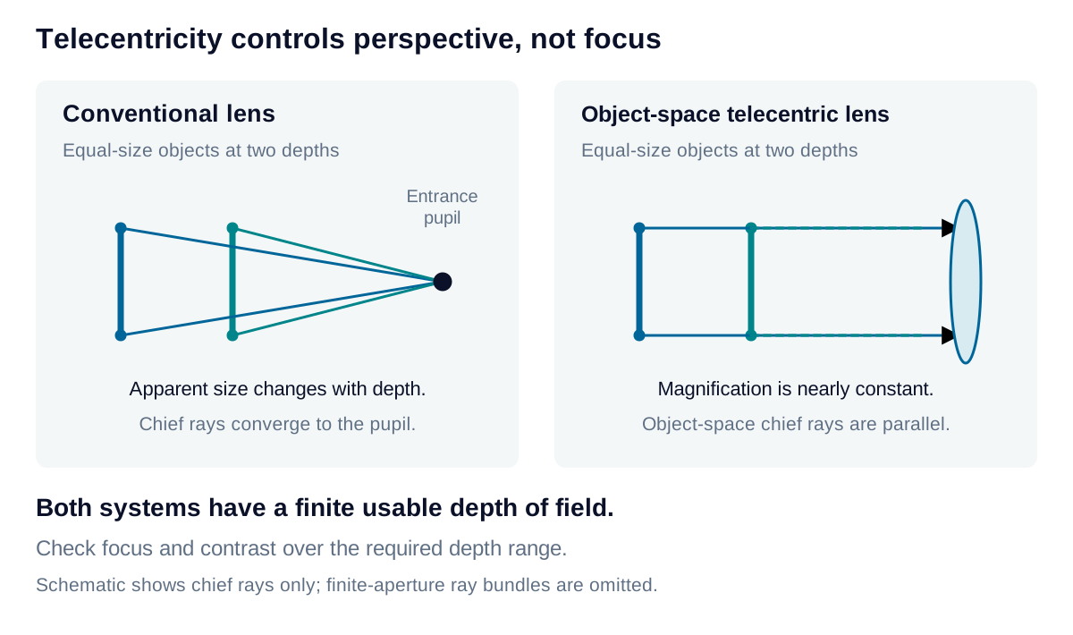
Reducing the aperture can increase depth of field and reduce some aberrations. It also reduces light throughput, and diffraction eventually lowers fine-detail contrast. The acceptable depth range depends on the image-quality criterion used at the near and far part planes.
Object-space telecentric optics reduce perspective and depth-dependent magnification within their specified operating range. Distortion and defocus remain separate considerations. Dimensional verification with independent references establishes residual error across the working volume, including the effects of mounting and focus tolerances.