
Illumination produces feature contrast through the interaction of light with the part. Reflection, transmission, absorption, and emission can each reveal different information. The useful arrangement depends on shape, finish, material response, and the feature being inspected. Early lighting trials help establish the camera’s spectral requirements, available viewing geometry, and exposure range.
Lighting geometry
Source position changes which surfaces return light to the camera. Common arrangements include:
- Backlight: a bright background produces silhouettes for edge, hole, and outline measurements. Translucency and divergent rays can affect the apparent edge; collimation may improve demanding gauging.
- Coaxial bright field: light returned from a flat reflective surface forms a bright background. Marks and local slopes change that return, while part tilt can change the entire image.
- Low-angle dark field: scratches, burrs, and raised features can redirect light toward the camera against a dark background. Visibility depends on feature orientation and source direction.
- Diffuse dome: illumination from a broad range of directions reduces concentrated reflections on glossy, curved surfaces. This can also reduce the contrast of useful texture.
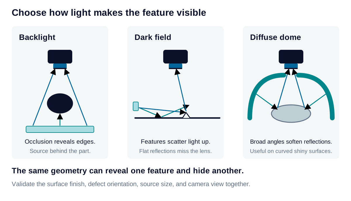
Good, defective, and borderline samples reveal how each arrangement responds to variations in finish, position, and orientation. Full-field coverage is also part of this comparison.
Wavelength and filtering
Spectral differences between a feature and its background can improve separation. The chosen band must be supported by the source, lens, filter, and sensor. A bandpass filter reduces out-of-band ambient light, while ambient energy within the passband remains. Polarization can suppress glare when the desired signal retains a distinguishable polarization response.
Fluorescence imaging uses an excitation band to generate emission from the part. The camera filter rejects excitation light and transmits the desired emission.
Motion and exposure
For constant lateral motion across an approximately uniform object sampling scale:
is allowable motion smear in pixels, is actual sampling along motion in mm/pixel, and is speed in mm/s. The resulting time limit is in seconds. At 0.5 pixel, 0.0495 mm/pixel, and 300 mm/s, it is 82.5 µs. Defocus, vibration, and other blur contributions require separate assessment.
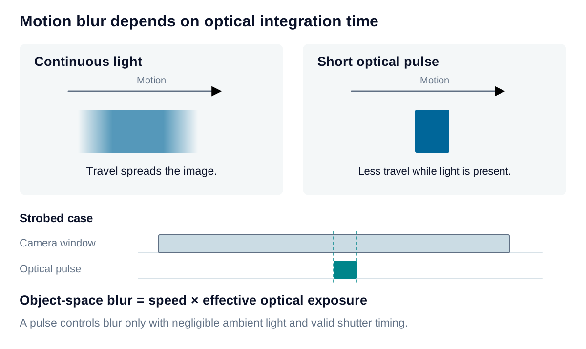
A short light pulse defines effective exposure when it dominates the recorded signal and fits the camera’s exposure window. Ambient light collected during a longer exposure can add a blurred contribution. For a rolling shutter, the pulse must fit within the common exposure window of the required rows to avoid partial illumination; trigger delay and jitter affect this timing.
Source current and pulse duration must provide adequate signal without saturation, within the rated duty cycle and thermal limits.