
Sensor specification connects the inspection area to the detail that must appear in the image. Usable pixel count determines spatial sampling, while active sensor dimensions and pixel pitch determine the required lens magnification. Optical contrast, noise, and calibration also influence performance, so sampling and measurement accuracy remain separate requirements.
Inspection field
The required field of view includes the part and its full range of positions. For each axis:
is maximum part extent in mm, and is the one-sided allowance for symmetric position variation. The dimensionless overscan fraction enlarges the total envelope. Thus, adds 10% overall. An 80 × 50 mm part with mm variation on each axis and 10% overscan requires a 92.4 × 59.4 mm field.
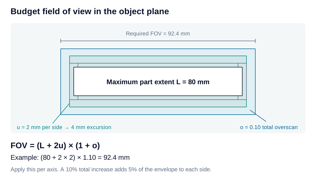
For asymmetric position variation, is replaced by the full minimum-to-maximum excursion. Trigger variation, fixture tolerance, geometric correction, and processing borders may require additional coverage. Assigning each contribution explicitly avoids counting the same allowance twice.
Feature sampling
A preliminary sampling target follows from the feature width and the chosen number of pixels across it:
is feature width in mm, is the selected pixel span, and is object-space sampling in mm/pixel. and are usable pixel counts along the corresponding axes. The ceiling operation rounds each requirement upward to an integer.
For a 0.30 mm feature spanning five pixels, the target is 0.060 mm/pixel. Covering the example field at this sampling requires at least 1,540 × 990 usable pixels.
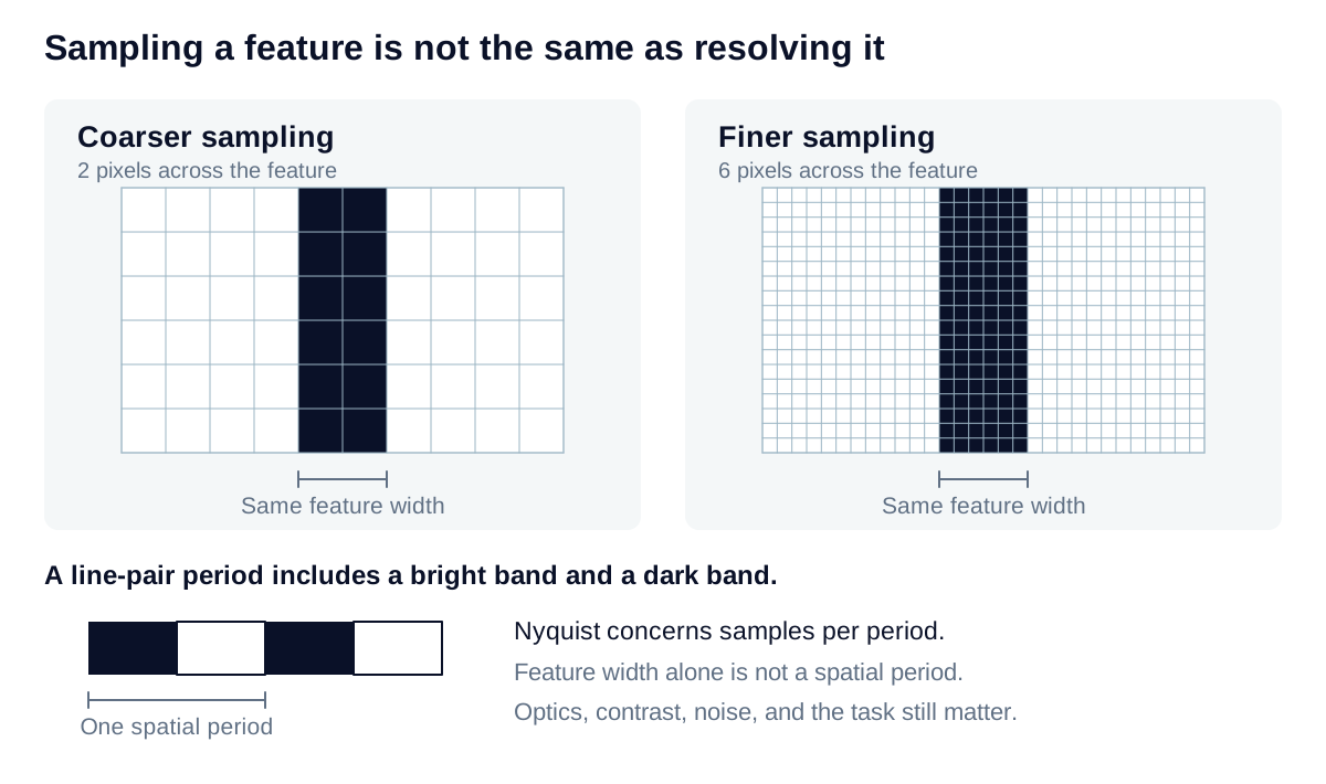
Three pixels across a favorable high-contrast feature can serve as an initial detection target; discrimination may require five or more. These empirical starting values depend on orientation, contrast, blur, noise, and the algorithm. Nyquist sampling concerns spatial frequency and does not establish a universal pixel count across an arbitrary defect.
Sensor performance
The sensor’s aspect ratio affects field coverage. With one common magnification, the limiting axis sets actual sampling; the other axis may capture a larger field than required. The candidate lens and sensor therefore need a combined coverage calculation.
Quantum efficiency at the illumination wavelength, read noise, and usable saturation determine the available signal range. Analog-to-digital converter bit depth describes digitization and does not by itself establish usable dynamic range. Shutter timing affects moving scenes and pulsed illumination, especially when sensor rows have different exposure windows.
Representative images at the intended exposure and field positions provide the basis for assessing feature visibility and measurement behavior. Sustained image delivery also needs confirmation in the selected camera mode.