
01 / 04   Interference & coatings

Application note

Controlling Reflection with Thin-Film Interference

Connect refractive index, optical thickness, and phase to antireflection coatings and multilayer filters.

An optical coating changes how a surface transmits, reflects, and absorbs light. Its response depends on the material at each interface and the phase accumulated between interfaces. A film that suppresses reflection at one wavelength can enhance it elsewhere, so a useful coating specification always includes the operating spectrum and illumination geometry.

Match amplitudes and phases

At normal incidence, the power reflectance of a bare interface between transparent media is:

Rbare=(n0−nsn0+ns)2R_{\mathrm{bare}}=\left(\frac{n_0-n_s}{n_0+n_s}\right)^2

Air against glass with ns=1.52n_s=1.52 reflects about 4.26% at that one surface. Adding a transparent film creates two interfaces and multiple internally reflected waves. An intermediate index helps set their amplitudes; the film’s thickness sets their relative phase. Both determine the total reflection.
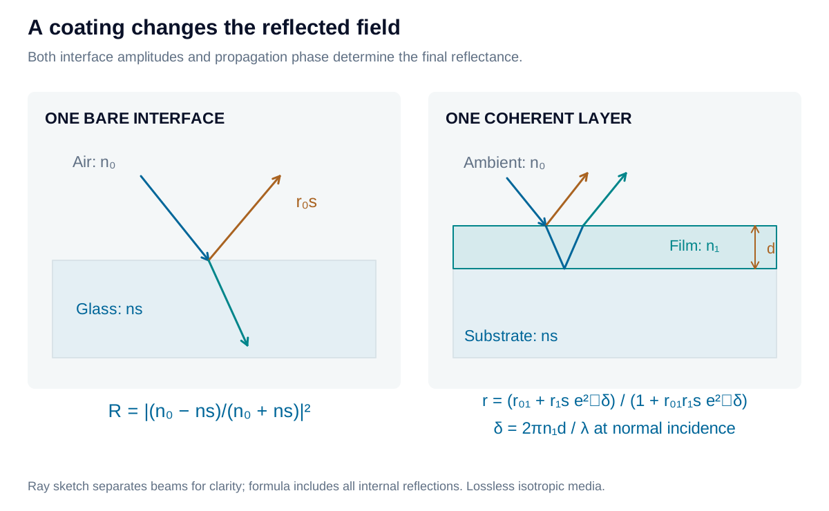
A dielectric film introduces reflected waves at two interfaces; their combined field depends on amplitude and propagation phase.

View diagram at full size

For a film of index n1n_1 and physical thickness dd, the normal-incidence optical thickness is n1dn_1d. The one-way phase thickness is δ=2πn1d/λ\delta=2\pi n_1d/\lambda, using vacuum wavelength λ\lambda. Reflection from the lower interface adds a round trip through the film, as well as the phase changes associated with reflection.

Start with a quarter-wave AR layer

An ideal single-layer antireflection coating at wavelength λ0\lambda_0 satisfies:

n1=n0ns,n1d=λ04n_1=\sqrt{n_0n_s},\qquad n_1d=\frac{\lambda_0}{4}

Quarter-wave optical thickness, or QWOT, gives a half-wave propagation difference between successive returned beams. The matching-index condition supplies the required amplitude balance. Together they yield zero reflectance in this lossless, planar, normal-incidence model.
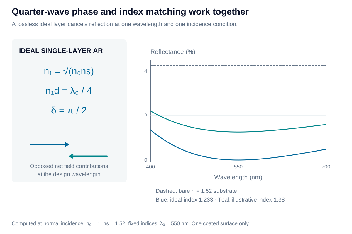
Quarter-wave optical thickness produces a reflection minimum when the layer index also matches the entrance and substrate media.

View diagram at full size

For air and ns=1.52n_s=1.52, the ideal index is approximately 1.233. A practical material may have a different index and leave residual reflection. Absorption, dispersion, oblique incidence, and deposition variation also change the result. The substrate’s rear surface needs separate treatment.

Calculate the complete single-film reflection

For real, positive refractive indices at normal incidence, define the electric-field reflection amplitudes r01=(n0−n1)/(n0+n1)r_{01}=(n_0-n_1)/(n_0+n_1) and r1s=(n1−ns)/(n1+ns)r_{1s}=(n_1-n_s)/(n_1+n_s). Summing the successive coherent reflections gives:

r=r01+r1se2iδ1+r01r1se2iδ,R=∣r∣2r=\frac{r_{01}+r_{1s}e^{2i\delta}}{1+r_{01}r_{1s}e^{2i\delta}},\qquad R=|r|^2

At δ=π/2\delta=\pi/2, this becomes:

RQW=(n0ns−n12n0ns+n12)2R_{\mathrm{QW}}=\left(\frac{n_0n_s-n_1^2}{n_0n_s+n_1^2}\right)^2

Thus quarter-wave thickness alone does not guarantee complete cancellation. A zero-thickness film or an integer half-wave film returns the bare-interface reflectance at that wavelength. This expression assumes a semi-infinite substrate and excludes a second coated or uncoated rear face.

Build a multilayer response

Alternating higher- and lower-index dielectrics, such as tantalum pentoxide and silica, provide a common design framework. A sequence of quarter-wave H/L pairs forms a Bragg reflector: the reflected contributions reinforce over a stopband. Adding pairs strengthens rejection; increasing index contrast generally broadens that band.

A resonant spacer between reflecting stacks introduces a transmission band. Coupled cavities and adjusted layer thicknesses then shape its width, ripple, and transitions. A simple quarter-wave reflector is therefore a building block, rather than a finished narrowband telecom filter.
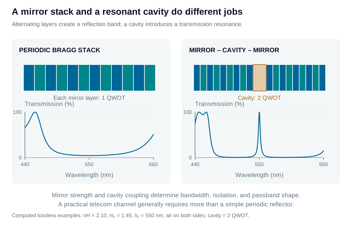
Alternating quarter-wave layers form a reflector; a resonant spacer between reflecting stacks creates a transmission band.

View diagram at full size

Connect the model to deposited material

Evaporation and sputtering are physical vapor deposition processes. Chemical vapor deposition and atomic layer deposition provide other growth mechanisms. Process conditions affect the deposited index, absorption, density, and stress; material names alone do not define those properties. Metals and graded-index coatings extend the design options beyond alternating transparent layers.

Iris Optics can connect coating requirements with illumination geometry, material assumptions, and practical verification so that the specified response supports the complete optical system.

Explore the coating

A quarter-wave antireflection layer

Compare a bare interface with a single quarter-wave dielectric layer. Change the layer index to see why phase cancellation also needs matched amplitudes.

Physical quarter-wave thickness
99.638 nm
Ideal matching-layer index
1.2329
Bare-interface reflectance
4.258 %
Coated reflectance at design wavelength
1.2601 %

The layer thickness is recalculated to remain quarter-wave at the design wavelength. Matching the phase condition alone does not guarantee zero reflection.

A quarter-wave antireflection layer: interactive plotPower reflectance / % against Vacuum wavelength / nm. Quarter-wave layer; Bare interface.2861.02445.51.896052.759764.53.6289244.498Vacuum wavelength / nmPower reflectance / %
Quarter-wave layerBare interface
Formula & assumptions

d = λ₀/(4n₁); ideal n₁ = √(n₀ns). R(λ₀) = [(n₀ns − n₁²)/(n₀ns + n₁²)]².

Normal incidence; homogeneous, isotropic, lossless layers and real, wavelength-independent indices. The substrate is semi-infinite: its rear surface is excluded. The ideal index may not be available as a durable deposited material. Values are teaching inputs, not a material database. The curve is calculated with coherent multiple reflections, not just two rays.

Explore the coating

Build a quarter-wave Bragg reflector

Explore how index contrast and pair count change the reflection band of an ideal repeated high/low-index stack.

Reflectance at design wavelength
96.957 %
High-index physical thickness
65.476 nm
Low-index physical thickness
94.828 nm
Infinite-stack frequency gap Δν/ν₀
23.445 %

12 lossless layers, illuminated through H first. This computed stopband is a reflector seed; no cavity or narrow channel passband is present.

Build a quarter-wave Bragg reflector: interactive plotPower / % against Vacuum wavelength / nm. Reflection R; Transmission T.2860445.52560550764.575924100Vacuum wavelength / nmPower / %
Reflection RTransmission T
Formula & assumptions

nH dH = nL dL = λ₀/4. At λ₀, Y = ns(nH/nL)^(2N), R = [(n₀ − Y)/(n₀ + Y)]². Infinite-periodic fractional frequency gap: Δν/ν₀ ≈ (4/π) asin[(nH − nL)/(nH + nL)].

Incident order is (HL)^N, ending in L at a semi-infinite substrate; normal incidence and constant real indices. The gap estimate is for an ideal infinite periodic medium, not a finite filter’s FWHM or guaranteed rejection interval. No absorption, scattering, rear-surface reflection, fabrication error, or material dispersion. A Bragg stopband alone is not a narrow telecom passband.

From estimate to application

Match the coating to the optical interface.

Iris Optics can help connect wavelength, angle, polarization, substrate, and environmental requirements to a practical coating specification.

Discuss your coating application