
02 / 03   Thickness & index

Application note

Measuring Thickness and Refractive Index

Separate geometric thickness from optical path, and use independent gaps to resolve an unknown material.

Thickness is a separation between two defined surfaces. A sensor may report physical distance, apparent focus position, optical path, or a material-corrected thickness. Establish which quantity the output represents before subtracting two interface readings or applying a refractive index.

Optical path is not geometric depth

For normal-incidence delay ranging through a uniform transparent layer, let LL be its one-way optical-path length after the instrument’s path convention is resolved:

L=ngt,t=Lng,ΔOPD=2ngtL=n_g t,\qquad t=\frac{L}{n_g},\qquad \Delta OPD=2n_g t

Here tt is physical thickness and ngn_g is group index; the last expression is the raw round-trip optical-path separation. Phase measurements instead use phase index at the relevant wavelength. A paraxial apparent-depth measurement follows a different relation, approximately dapparent=t/nd_{\mathrm{apparent}}=t/n. Chromatic confocal thickness therefore requires the sensor’s calibrated material and optical model, rather than a universal “divide by index” rule.
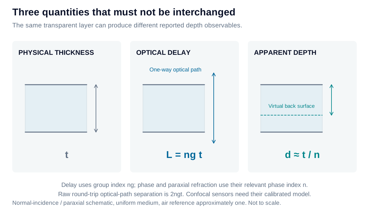
Geometric thickness, interferometric optical delay, and apparent depth are distinct quantities with different refractive-index corrections.

View diagram at full size

Measure opaque parts from opposing sides

Two facing sensors measure distances d1d_1 and d2d_2 from reference planes separated by a calibrated baseline BB:

t=B−d1−d2t=B-d_1-d_2

This works for accessible opaque surfaces when both returns remain valid. The spots must correspond to the intended thickness direction and lateral location. Frame expansion, unequal tilt, asynchronous readings, and separated spots on a moving or wedged part create thickness errors even when each sensor is repeatable.
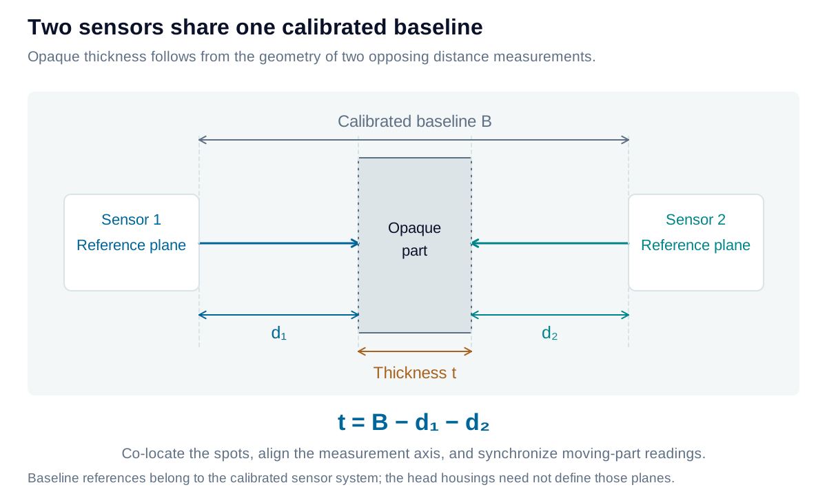
Two opposed sensors measure the near and far surfaces of an opaque part relative to a calibrated baseline.

View diagram at full size

Use air gaps to resolve unknown glass

A flat base and supported cover glass establish a cavity height HH, measured from the cover’s lower face to the base. Measure the empty cavity, then place the unknown transparent specimen on shorter inner supports and replace the cover without changing its reference geometry.

Let aa be the air gap above the specimen and bb the air gap below it. Independently resolved interface delays isolate these air gaps, so:

t=H−a−b,neff=LH−a−bt=H-a-b,\qquad n_{\mathrm{eff}}=\frac{L}{H-a-b}

The optical thickness LL comes from the specimen’s two interfaces. A delay measurement yields an effective group index for the instrument’s spectrum; it does not independently establish phase index or a complete dispersion curve. Gauge-block heights provide a geometric cross-check, provided contact, cleanliness, parallelism, and cover deflection are controlled.
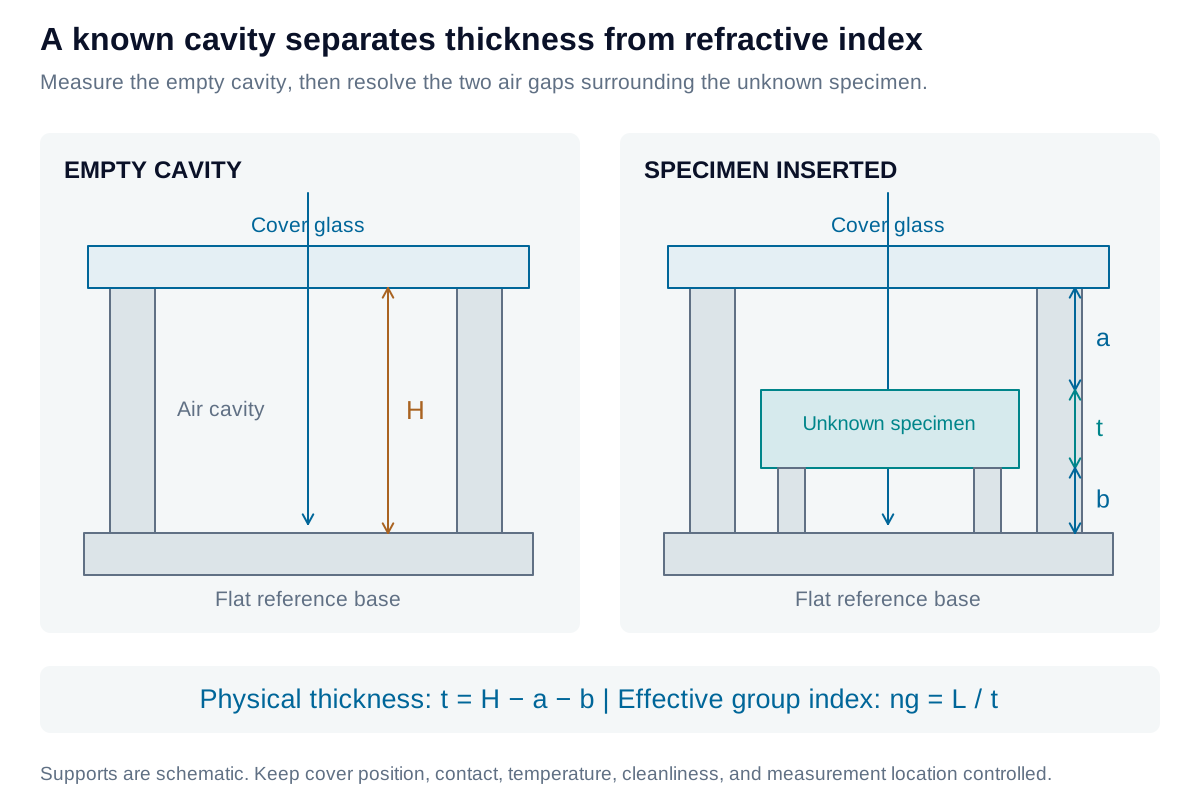
An empty cover-glass cavity establishes H. With the specimen inserted, measured upper and lower air gaps leave its physical thickness as H minus a minus b.

View diagram at full size

Why adjacent interface delays isolate each layer

Consider one-way cumulative optical-path coordinates q0,q1,q2,q3q_0,q_1,q_2,q_3 for the cover’s lower surface, specimen top, specimen bottom, and base. With air index nan_a:

q1−q0=naa,q2−q1=ngt,q3−q2=nabq_1-q_0=n_a a,\quad q_2-q_1=n_g t,\quad q_3-q_2=n_a b

Common upstream paths cancel in each adjacent difference. Divide air-path differences by nan_a to obtain geometric gaps. If the instrument reports round-trip optical path, first divide those differences by two. The cover’s own optical thickness cancels only when the same correctly identified lower interface is used.

The empty-cavity separation gives H=(qbase,empty−qcover,empty)/naH=(q_{\mathrm{base,empty}}-q_{\mathrm{cover,empty}})/n_a. Subtracting the two occupied-cavity gaps leaves the specimen thickness. The method needs independently resolved layer delays: arbitrary interference peaks can represent pairwise paths, multiple reflections, or processing artifacts, rather than a simple ordered list of surfaces.

The inferred index becomes sensitive to gap errors when H−a−bH-a-b is small. For independent input uncertainties, ut2=uH2+ua2+ub2u_t^2=u_H^2+u_a^2+u_b^2 and:

un2≈(uLt)2+(L utt2)2u_n^2\approx\left(\frac{u_L}{t}\right)^2+ \left(\frac{L\,u_t}{t^2}\right)^2

Shared references and common fitted peaks can correlate these inputs; the full uncertainty calculation must then retain covariance terms. The calculator shows the geometry, not a complete instrument uncertainty budget.
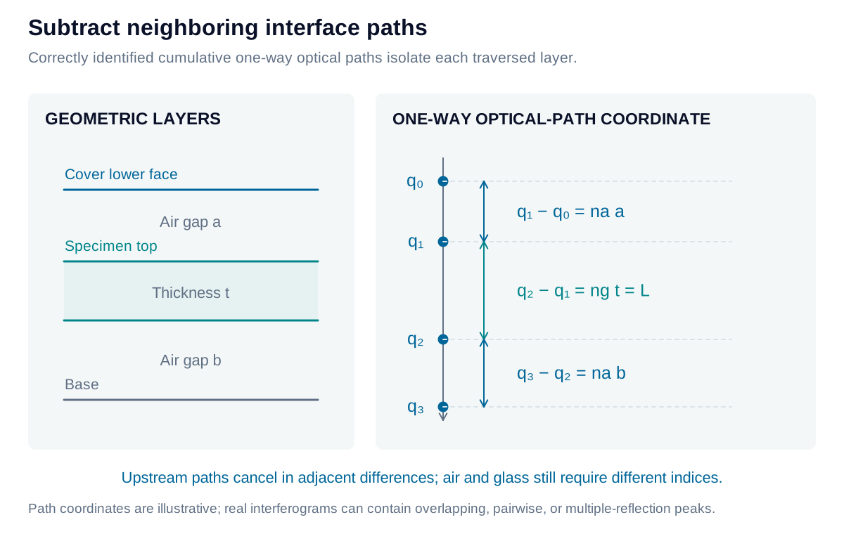
Resolved cumulative optical-path coordinates show which neighboring interface differences belong to each air gap and to the specimen.

View diagram at full size

Validate the interfaces, not only the arithmetic

Weak or overlapping reflections, absorption, coatings, wedge, dispersion, and multiple reflections can prevent reliable layer identification. A suitable multilayer interferometer may support this method; a generic CSI topography camera or chromatic confocal sensor is not guaranteed to expose all required paths. Working range and angular tolerance are implementation-specific.

Iris Optics can develop transparent and opaque thickness measurements, test interface separability, and establish the calibration and uncertainty model needed for material or production acceptance.

Explore the measurement

Convert an interface separation to thickness

The same pair of interfaces produces different numerical separations depending on what the instrument reports.

Physical thickness
1 mm
One-way optical thickness
1.5 mm

A coherence envelope or spectral group-delay separation normally requires group index. Confirm whether the instrument has already converted round trip to one way.

Convert an interface separation to thickness: interactive plotPhysical thickness / mm against Appropriate refractive index. Fixed reported separation; Entered index.0.9040.61641.2520.85361.61.0911.9481.3282.2961.565Appropriate refractive indexPhysical thickness / mm
Fixed reported separationEntered index
Formula & assumptions

One-way: t = L/n. Round-trip: t = OPD/(2n). Paraxial apparent depth in air: t = n dapp.

Normal viewing of a homogeneous transparent layer with correctly assigned, resolved interfaces. Use group index for the delay/envelope model and phase index for the paraxial refraction model. Real high-NA chromatic-confocal thickness calibration is not this apparent-depth formula. A vendor’s already-corrected physical thickness must not be corrected a second time.

Explore the measurement

Thickness from opposed sensors

Subtract two synchronized surface distances from a calibrated separation between the sensor reference planes.

Physical thickness
7 mm
Calibrated separation
100 mm
Thickness from opposed sensors: interactive stack diagramFront gap d₁: 45 mm; Part thickness t: 7 mm; Back gap d₂: 48 mmPhysical axial extent: 100 mmFront gap d₁45 mmPart thickness t7 mmBack gap d₂48 mmAxial geometry only; lateral dimensions are schematic.
Formula & assumptions

t = B − d₁ − d₂.

Distances are geometric, in the same coordinate system, and within each sensor’s calibrated range. Axes must address corresponding locations with the specified orientation. Head housings are not automatically the reference planes. Synchronization, thermal drift, tilt and surface-dependent offsets contribute to uncertainty; arbitrary opposite-facing sensor pairs are not automatically a thickness gauge.

Explore the measurement

Recover thickness and group index from air gaps

Use an empty calibrated cavity, two air gaps around the sample, and its one-way group optical thickness.

Physical thickness t
1 mm
Inferred group refractive index ng
1.52
Total physical air-gap height
4 mm

The displayed stack uses physical lengths. The optical thickness Lg is a separate delay measurement; it is not drawn as an extra physical layer.

Recover thickness and group index from air gaps: interactive stack diagramUpper air gap a: 2 mm; Unknown sample t: 1 mm; Lower air gap b: 2 mmPhysical axial extent: 5 mmUpper air gap a2 mmUnknown sample t1 mmLower air gap b2 mmAxial geometry only; lateral dimensions are schematic.
Formula & assumptions

t = H − a − b; ng = Lg/t.

H, a and b are physical air-gap lengths, with air index and round-trip scaling already corrected. Lg is the sample’s one-way group optical thickness. The cover/reference geometry must remain stable and the sample must fit without contact with the cover. Resolve the correct interface peaks along a consistent near-normal ray path; coating, multiple-reflection ghosts, sag and dispersion can invalidate simple peak assignments. This does not infer phase index at one wavelength or invert raw chromatic-confocal readings.

From estimate to application

Turn interface measurements into a defensible thickness result.

Define the optical path convention, material index, fixture geometry, and calibration needed for your transparent or opaque part.

Review your thickness measurement